

An injection mould looks like a solid block of steel, but inside it is a stack of plates, pins and pillars that each do one job. Take one of our own tools apart below and see what every part is for.
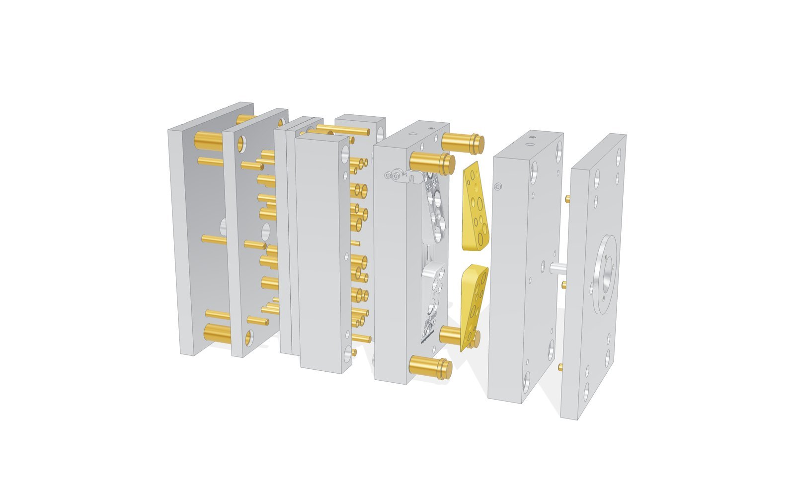
The model is FORM197, one of our own tools, drawn straight from its CAD file with every size as modelled. It makes two door stops per shot in a yellow rubbery material. Steel is shown in silver, and the screws, pins and pillars in gold so you can pick them out. In the real tool they are steel too.
The Two Halves of a Mould
Every injection mould splits into two halves that meet at the parting line. The fixed half bolts to the press platen nearest the injection unit, and molten plastic enters through it. The moving half bolts to the platen that opens and closes, and it carries the system that pushes the finished parts out.
Each shot runs the same way. The press clamps the halves together, plastic is injected into the cavities, it cools against the water-cooled steel, the moving half opens, and the ejectors push the parts off. On this tool that cycle makes two parts at a time, because it is a two-cavity mould.
The Parts, One by One
Moving clamp plate
The 27 mm plate at the back of the moving half. At 246 mm wide it stands 25 mm proud of the stack on each side, which is where the press clamps hold it to the platen. Six long M12 cap screws run from here through the moving half and hold it together.
Core-pin plate and core pins
A 22 mm plate behind the ejector plates holds 16 core pins. They never move. Each one runs up through the ejector system into the part and forms the hole down the middle of a boss.
Spacer rails
Two rails, 76 mm tall, hold the B plate away from the clamp plate. The gap they leave is the room the ejector plates need: the two ejector plates are 39 mm together, so they have up to 37 mm of travel.
Ejector plates and sleeves
When the mould opens, the press pushes these plates forward. On this tool they carry hollow ejector sleeves, each one sliding over a core pin, so the sleeves push the bosses off the pins evenly instead of pulling them out of shape. Return pins push the plates back before the mould closes again. Sleeve ejection like this is a good choice for parts with deep round bosses.
B plate and guide pillars
The 79 mm B plate carries the cores, which form the inside of each part. On this tool the cores are machined straight into the plate rather than into separate inserts. Four guide pillars, 35 mm across, run from the B plate into the A plate so the halves line up before the steel faces touch.
The moulded parts
Two door stops, each 66 × 137 × 27 mm, with raised lettering and round bosses. The plastic fills the gap between the cores and the cavities. When the mould opens, the parts stay on the cores until the sleeves push them off.
A plate
The 56 mm A plate has the two cavities cut into it, so its surface finish becomes the outside of the part. A polished cavity makes a glossy part; a textured cavity makes a matt or grained one.
Fixed clamp plate and locating ring
The 27 mm plate at the front bolts to the fixed platen. The Ø125 mm locating ring centres the whole mould on the press, so the press nozzle meets the sprue, where plastic enters the tool, dead square.
What an Injection Mould Is Made Of
Every tool is specified for its own job: the plastic, the part and how many you need. These are the usual choices for a mould built like this one.
| Part | Typical material | Why |
|---|---|---|
| Clamp plates, spacer rails, ejector plates | Carbon steel (1.1730 / C45) | They carry load but never touch the plastic, so they stay soft and economical. |
| A and B plates with cores and cavities cut in | Pre-hardened tool steel (P20 type, 1.2311 or 1.2738, about 30–34 HRC) | Hard enough for long runs, but machined without heat treatment, which keeps lead times short. |
| Cavity inserts on long-running tools | Hardened hot-work steel (1.2343, about 48–52 HRC) | Holds an edge and a polish over hundreds of thousands of shots. |
| Core pins, ejector pins and sleeves | Hardened and nitrided steel (often 1.2344) | A hard skin for parts that slide every cycle. |
| Guide pillars and bushes | Case-hardened steel (1.7131) | A hard wearing surface on a tough core. |
| Screws | High-tensile cap screws (12.9 grade) | Hold the plates together under clamping and injection forces. |
How a Mould Tool Is Made
- Design and fill simulation. The part and tool are modelled in CAD, and a Moldex3D mould flow analysis checks how the cavities fill, where the gates go and how the cooling should run.
- Mould base. The plates arrive ready-ground in catalogue sizes and grades.
- Machining. Cores and cavities are CNC-milled into the plates or inserts, and the cooling channels are drilled round them.
- Spark erosion (EDM). Sharp inside corners, deep ribs and lettering are eroded with shaped electrodes where a cutter can't reach.
- Pins and sleeves. Core pins, ejector pins and sleeves are cut and ground to length so each ends exactly where it should.
- Polish or texture. The cavity surfaces get the finish the part needs.
- Fit and assemble. Shut-off faces are spotted in, the guide pillars, pins and sleeves fitted, and the water circuits pressure-tested.
- First shots. The tool runs on a press, the parts are measured, and the steel is corrected until they are in tolerance.
All of this happens in our own toolroom in Haverhill: see mould tool design and mould toolmaking.
Other Mould Layouts
This is a two-plate mould: it opens at one parting line. A three-plate mould opens at two, so the runner can be separated from the parts automatically. A hot runner mould keeps the plastic molten all the way to the part, so no runner is moulded at all. Parts with undercuts need sliders or lifters that move sideways as the mould opens. Which layout suits your part depends on its shape, the plastic and the volumes, and it is something we work out with you at the design stage.
Sources & Further Reading
For independent background on the process, see the British Plastics Federation's guide to injection moulding and the overview on Wikipedia.